Our new paper on using AFM-IR to analyze aging in paint is out in Angewandte Chemie.
In this paper first authored by Xiao Ma from the National Gallery of Arts (Washington, D.C.). Here, we looked at paint that had been painted onto a canvas 23 years ago. Instead of repeating the contents of the paper again, I would like to write a bit about some of the measurement details not found in the publication.
One of the more challenging parts of this work was sectioning the canvas thin enough to be easily measurable with AFM-IR. In AFM-IR, the sample thickness influences spatial resolution. Furthermore, initial tests showed us pretty quickly that measurements on thick (> 1 mm) sections were close to impossible. Here, the embedding resin began to visibly melt when we tuned to laser to one of its absorption bands, even before we got a decent signal on the paint sample.
The measurements in the paper were performed on 200 nm thick samples, but even on sections as thick as 1 µm decent results were obtained.
Even though the section ended up being on average about 200 nm thick, they were still somewhat rough (for AFM standards) at the end because of their very heterogeneous makeup (organic goo and inorganic crystals). This meant, that our first tests using contact mode AFM-IR failed miserably: all images showed strong correlations between the topography and the structure no matter how slow we went. Furthermore, after a certain point during each measurement, all AFM-IR spectra started to look very similar - a telltale sign that the AFM tip had been contaminated.
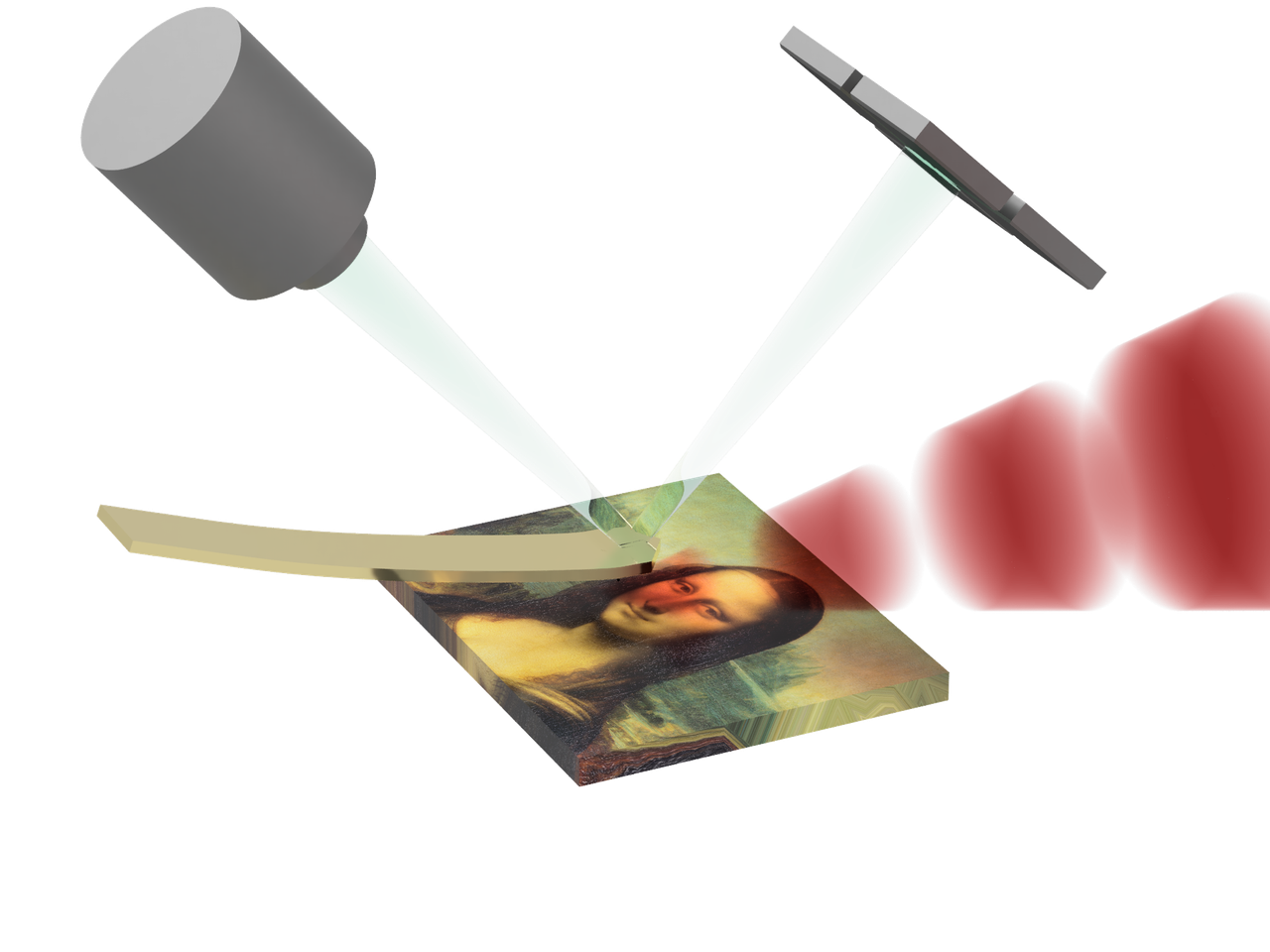
Tapping mode AFM-IR
Luckily, tapping mode AFM-IR had become available by that time. This method worked significantly better for cross sections and only measurements using that technique made it into the final paper.
Tapping mode AFM-IR uses a heterodyne measurment principle to enhance the AFM-IR signal and make is measurable in tapping mode. Heterodyning is a rather old princliple that stems from the dawn of telegraphy in 1901. It’s underlying working principle lies in a basic trigonometric identity:
Heterodyning has two functions:
It shifts the frequency of a signal from one frequency range to another
It enhances a weak signal
Heterodyne detection needs a so called “mixer”, a step in the signal chain, that has a quadratic response to the drive signal. In case of the AFM this is the force-distance curve \(F(z)\) . This function converts the distance between he AFM tip and the sample ( \(z\) ) into a force onto the AFM tip. In the case of a tapping mode AFM measurement \(z= A_{tap} \cos(2 \pi f_1) + A_{IR} \cos(2 \pi f_2) + z_0\) . Where \(A_{tap}\) is the amplitude of the tapping motion, \(A_{IR}\) is the amplitude of the height change of the surface due to laser heating (which we approximate with a sine wave here) and \(z_0\) is the distance between the cantilever equilibrium position and the surface. \(f_1\) and \(f_2\) are the tapping drive frequency and the laser repetition rate, respectively.
When we approximate the force distance curve with a polynomial series
Looking just at the second order term, we get:
which includes our heterodyne term and two square terms, which lead to oscillations at \(2 f_1\) and \(2 f_2\).
For tapping AFM-IR, \(f_1\) (tapping drive frequency) and \(f_2\) (laser rep rate) are tied to the mechanical properties of the cantilever. The cantilever acts as a force transducer and translates the tip sample force into a deflection signal. However, the gain of this transduction is frequency dependent - at the mechanical resonance a smaller force modulation leads a larger deflection amplitude. \(f_1\) is set to one of the mechanical resonances. Thus, in order to sensitively detect the heterodyne signal, either \(f_1 - f_2\) or \(f_1 + f_2\) has to be set to one of the other resonances of the cantilever.
As far as I can tell so far, active tracking of the resonance is not strictly necessary in tapping mode AFM-IR, but there are other sources of artifacts. But that is stuff for another blog post.